Aircraft Electrical Wiring
This advice on routing and installing aircraft
electrical
wiring is specific to construction of a Vans RV-8, but builders of
other kitplanes will also find it useful.
For the most part, my
wire routing is from the front right firewall where my battery is
located, to the circuit breakers on the F-8101 right console.
Then forward into the right gear box, across the F-802T L.G. box upper
brace, into the left gear box and to the switches on the throttle
quadrant.
From there they run through the left gear box, under the F-881PP-L mid
cabin cover, through the main wing spar, and back the left side of the
aircraft.
I ran my aircraft electrical wiring for the wing tank
senders down the respective right gear boxes, then under the
mid
cabin panels, and out the side of the fuselage to the tanks.
I
used a small rubber grommet for the hole through the fuselage.
I’m
happy with the way the wiring turned out, except for right behind the
panel. If I were doing it again, I would change my aircraft
electrical wiring slightly to make removing the main panel
easier.
(See
what I would do different)
My Wire Routing
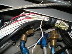
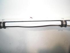
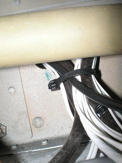
Wire bundle just aft of gear box
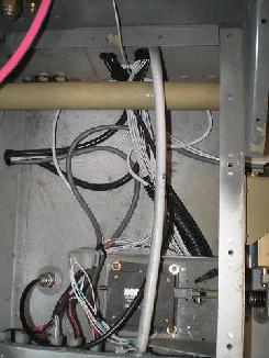
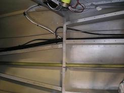
Aft cabin
floor wires
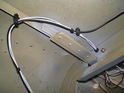
Flap wire and
GPS antenna
Forward right
wires
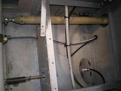
Two images of the wiring bundle just aft of the main spar
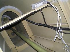
Aft fuselage
wires
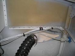
Forward left
wires
There were two spots that were a little difficult
to work with while running the wires. Here are some thoughts
on them.
Bottom of the gear boxes
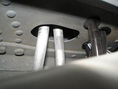 Because
I needed the return fuel line, I enlarged the hole at the bottom of the
F-802B-L bulkhead. When I ran the aircraft electrical wiring,
I
thought the extra hole I made would be enough. That wasn’t
the
case. I later realized the electric and pitot/static lines
wouldn’t all fit, and I would have to cut more holes. Had I
known
from the beginning how much stuff was going to run through here, I
would have made the hole bigger to start with, and could have achieved
a much cleaner look. Because
I needed the return fuel line, I enlarged the hole at the bottom of the
F-802B-L bulkhead. When I ran the aircraft electrical wiring,
I
thought the extra hole I made would be enough. That wasn’t
the
case. I later realized the electric and pitot/static lines
wouldn’t all fit, and I would have to cut more holes. Had I
known
from the beginning how much stuff was going to run through here, I
would have made the hole bigger to start with, and could have achieved
a much cleaner look.
I have two ideas how this could be done
better. The first is to make one hole large enough for
everything. The fuel lines would run through on their
own.
I would then use an adel clamp to hold the electric wires, and one each
for the pitot and static lines.
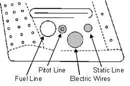 The
other idea is to make
several holes. But if this is planned out from the beginning,
they can be made the right size and location before the gearbox is
riveted together, or if it’s too late for that, drilled before anything
is installed. Two small holes with a rubber grommet would
each
hold the pitot and static lines. A third hole, slightly
larger,
again with the rubber grommet, would hold the aircraft electric
wiring. The fourth hole would allow the fuel lines to run
forward. The
other idea is to make
several holes. But if this is planned out from the beginning,
they can be made the right size and location before the gearbox is
riveted together, or if it’s too late for that, drilled before anything
is installed. Two small holes with a rubber grommet would
each
hold the pitot and static lines. A third hole, slightly
larger,
again with the rubber grommet, would hold the aircraft electric
wiring. The fourth hole would allow the fuel lines to run
forward.
Of course, a combination could also be
used. You can combine items into one hole and use clamps to
hold
things off the edges. Be careful not to squish the
pitot/static
lines.
Aft end of the main spar
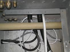 I
followed Vans instructions and drilled the electric and pitot/static
holes as described on plans OP-11 DETAIL G and DETAIL H. I
then
strung the corrugated conduit through the spar and aft under the
floor. There was no problem until I installed the W-816
aileron
pushrods. The conduit interfered and rubbed against the
pushrods
as they moved. I had to cut the conduit away so I could bend
the
wire bundle tight enough to keep it from rubbing. I turned it
90°
and clamped it to the spar, then ran it under the pushrods. I
followed Vans instructions and drilled the electric and pitot/static
holes as described on plans OP-11 DETAIL G and DETAIL H. I
then
strung the corrugated conduit through the spar and aft under the
floor. There was no problem until I installed the W-816
aileron
pushrods. The conduit interfered and rubbed against the
pushrods
as they moved. I had to cut the conduit away so I could bend
the
wire bundle tight enough to keep it from rubbing. I turned it
90°
and clamped it to the spar, then ran it under the pushrods.
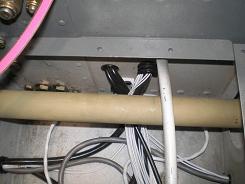
Aft end of
the main spar after corrections
Return
from Aircraft Electrical
Wiring to Aircraft
Electrical Systems
Return
from Aircraft Electrical
Wiring to Kit
Plane Advice Home
|




 Because
I needed the return fuel line, I enlarged the hole at the bottom of the
F-802B-L bulkhead. When I ran the aircraft electrical wiring,
I
thought the extra hole I made would be enough. That wasn’t
the
case. I later realized the electric and pitot/static lines
wouldn’t all fit, and I would have to cut more holes. Had I
known
from the beginning how much stuff was going to run through here, I
would have made the hole bigger to start with, and could have achieved
a much cleaner look.
 The
other idea is to make
several holes. But if this is planned out from the beginning,
they can be made the right size and location before the gearbox is
riveted together, or if it’s too late for that, drilled before anything
is installed. Two small holes with a rubber grommet would
each
hold the pitot and static lines. A third hole, slightly
larger,
again with the rubber grommet, would hold the aircraft electric
wiring. The fourth hole would allow the fuel lines to run
forward.
  I
followed Vans instructions and drilled the electric and pitot/static
holes as described on plans OP-11 DETAIL G and DETAIL H. I
then
strung the corrugated conduit through the spar and aft under the
floor. There was no problem until I installed the W-816
aileron
pushrods. The conduit interfered and rubbed against the
pushrods
as they moved. I had to cut the conduit away so I could bend
the
wire bundle tight enough to keep it from rubbing. I turned it
90°
and clamped it to the spar, then ran it under the pushrods.