|
Terra Comm/Nav/Trans
Aircraft
Radios
I installed Terra radios in my RV-8. But
it doesn't
matter which aircraft radios you install, or in which airplane you
install them.
These tips and ideas are applicable and may help you out.
Mechanical
Installation
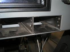 The
COMM and NAV aircraft radio trays were already connected, but I riveted
the TRANS tray
to them. I used a couple of AN426AD3 rivets. The
front ones
were easy to squeeze with the pneumatic squeezer. The tray
itself
got in the way to squeeze the rear ones, so I squeezed them with a
small C-clamp. I located the rivets using the preexisting
holes
if I could, since they were countersunk and would keep the rivet head
out of the way. The
COMM and NAV aircraft radio trays were already connected, but I riveted
the TRANS tray
to them. I used a couple of AN426AD3 rivets. The
front ones
were easy to squeeze with the pneumatic squeezer. The tray
itself
got in the way to squeeze the rear ones, so I squeezed them with a
small C-clamp. I located the rivets using the preexisting
holes
if I could, since they were countersunk and would keep the rivet head
out of the way.
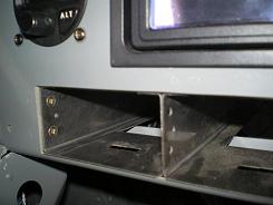 I
cut the square hole in the
instrument panel,
and set the aircraft radios and trays so they protruded the amount I
wanted. Then I marked the trays where the back of the
instrument
panel hit them. I used three pieces of angle iron to hold the
front of the trays to the panel. Two rivets through the panel
and
two into the tray. By doing the ones on the panel first, I
could
use the squeezer on the rivets that show. I
cut the square hole in the
instrument panel,
and set the aircraft radios and trays so they protruded the amount I
wanted. Then I marked the trays where the back of the
instrument
panel hit them. I used three pieces of angle iron to hold the
front of the trays to the panel. Two rivets through the panel
and
two into the tray. By doing the ones on the panel first, I
could
use the squeezer on the rivets that show.
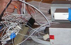 I
mounted
the back of
the trays to the F-802NPP L.G. Box Upper Brace with a screw.
I
thought I had located it where it would be easy to install and remove,
but it was harder than I thought. See What
I would do
different for this discussion. I
mounted
the back of
the trays to the F-802NPP L.G. Box Upper Brace with a screw.
I
thought I had located it where it would be easy to install and remove,
but it was harder than I thought. See What
I would do
different for this discussion.
Wiring
I
did almost all of the wiring at the bench. I wired the d-sub
connectors before I installed them in the trays, but I suppose you
could do it the other way around (see Helpful
Hints for Soldering Terminals).
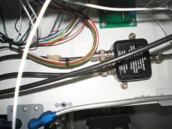 I made
the antenna
cables on the back of the COMM and TRANS about 12 inches long, and put
a BNC connector on them. This lets me disconnect the cables
easily if I want to pull the panel. I have only one antenna
for
nav and glide slope, so needed the Diplexer (VOR/GS/LOC), Vans Part
Number = AV CI-507. I mounted it on the backside of the
F-866APP
Baggage Compartment. I ran the antenna cables from the back
of
the aircraft radios to the diplexer without splices or connectors.
The
TRANS cable runs down the left gearbox, aft under the floor to the
antenna. The COMM and NAV cables run down the right gearbox,
aft
under the floor to the COMM antenna, and out to the right wingtip to
the NAV antenna.
Installing
the Antennas
I
used a doubler on the inside of the fuselage for the TRANS and COMM
antennas. The TRANS doubler was just a large aluminum
washer. I made the COMM doubler out of scrap aluminum that I
cut
to the same size as the base of the antenna. After drilling
the
center hole, I placed the antenna against the fuselage, marked and
drilled the holes. After repeating this for the doubler, I
then
fastened nutplates to the inside (top) of the doubler. Then I
screwed everything into place.
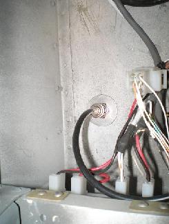
Inside trans
antenna
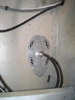
Inside comm
antenna
Wingtip Antenna
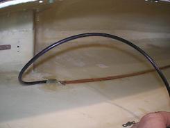 The
Van’s “AV ANTENNA W’TIP” amounted to a strip of metal
foil, some coax, and the connectors.
I
ran the cable through the wing and terminated on the last rib. Then for the antenna, I
cut the strip to
length, soldered on the coax, and glued it inside the wingtip. The
Van’s “AV ANTENNA W’TIP” amounted to a strip of metal
foil, some coax, and the connectors.
I
ran the cable through the wing and terminated on the last rib. Then for the antenna, I
cut the strip to
length, soldered on the coax, and glued it inside the wingtip.
Really, the only
difficulty was that the fiberglass resin
caused the sticky side of the metal strip to come undone, so it wanted
to curl
up instead of laying flat. I
used a few
strips of masking tape to hold the strip down until the resin set. I added another strip of
cloth across the top
of the coax so that the soldered joint didn’t take any abuse. I figured that this way,
the fiberglass strip
would take all the stress of the coax moving and flopping as I did
loops to
music.
Checking
things Out
Make
sure you use a good, clean power supply here. Either a real
power
supply, or a battery. Don’t use a trickle charger.
I made
sure the COMM all worked with the intercom and checked that the NAV
locked onto the local VOR. I’ll have to wait on the TRANS
until
the first flight. I don’t think ATC will be able to receive
my
signal on the ground.
Return
from Aircraft Radios
to Electrical
Systems
Return from Aircraft Radios to Kit Plane Advice Home
|


