|
Aircraft Throttle Quadrant
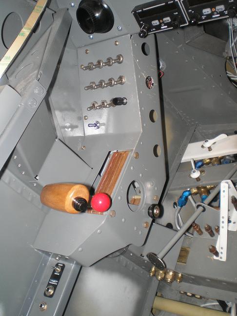
This homebuilt aircraft throttle quadrant
contruction advice is based on my customized quadrant for a Vans RV-8.
However,
builders of any kitplane will find ideas here that apply to them.
Why
customize?
 I
have short arms, and found the standard location of the aircraft
throttle was
too far forward and outboard. It was too uncomfortable for me
to
reach, so I felt like I was stretching to get to it. Since
it’s
my plane, it should fit me. I teamed with a friend
of mine
who also suffers from the same affliction, and we came up with our own
throttle quadrant that moved the throttle inboard and aft just enough
to make it comfortable. I
have short arms, and found the standard location of the aircraft
throttle was
too far forward and outboard. It was too uncomfortable for me
to
reach, so I felt like I was stretching to get to it. Since
it’s
my plane, it should fit me. I teamed with a friend
of mine
who also suffers from the same affliction, and we came up with our own
throttle quadrant that moved the throttle inboard and aft just enough
to make it comfortable.
Building the
Aircraft Throttle
Quadrant
 We
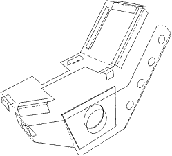
started with the F-864BPP Throttle Quadrant Cover as a template for our
cover. Using posterboard, we marked the F-864BPP, then added
the
extra thickness for the F-804 channel. We left it long enough
in
the front to play with. We then put it into the cockpit and
messed with the front until we were happy with the look as it mated to
the bottom of the F-803BPP-L Instrument Sub Panel. This gave
us
the angle for the front of the cover. We
started with the F-864BPP Throttle Quadrant Cover as a template for our
cover. Using posterboard, we marked the F-864BPP, then added
the
extra thickness for the F-804 channel. We left it long enough
in
the front to play with. We then put it into the cockpit and
messed with the front until we were happy with the look as it mated to
the bottom of the F-803BPP-L Instrument Sub Panel. This gave
us
the angle for the front of the cover.
To make the
side, we
traced the F-864 onto posterboard. The top was cut to shape
to
match the cover, and the bottom was cut to fit over the F-806A-L
forward arm rest. The slant was cut to a pleasing thickness,
lightening holes drilled, and the bottom turned in to provide rigidity.
The
cover is held to the side by an aluminum angle flush riveted to the
back sides of both. We then cut the F-864 to fit on the
inside of
the new cover and provide extra support to the throttle
assembly.
We did have to install longer screws into the four corners of the
throttle assembly since they were now going through the new cover and
what was left of the F-864.
Support and
attaching
We
used AA3-032 ¾ x ¾ to secure the outside to the skin above the F-864C.
More of the same AA was used to secure the front to the bottom of the
F-803BPP-L Instrument Sub Panel, and the back to the F-806A-L Forward
Arm Rest. We riveted all of the AA in place, and installed
nutplates to hold the aircraft throttle quadrant.
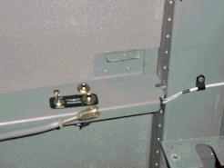
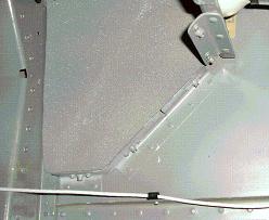
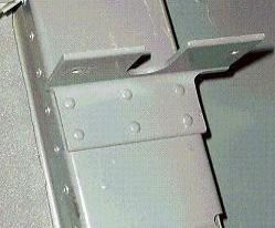
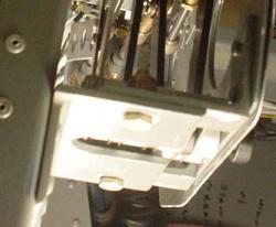
To support
the bulk of
the weight, we used some 2 x 2 ½ x 3/16 6061-T6 leftover from the T-405
tank attachment angle. My friend riveted his to the
F-804PP-L,
and I bolted mine. Two pieces of 3/16 aluminum angle are
riveted
to the side of the throttle quadrant to match up to the top of the
6061-T6 bracket. Two bolts secure the throttle quadrant to
the
bracket.
Rear
Seat Throttle Linkage
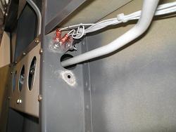 Because
I had moved the front throttle, the linkage to the rear seat needed
modifying too. I started by drilling the holes in the F-805-L
bulkhead as depicted in Template #1 provided with the Rear Seat
Throttle Kit. I bent a piece of scrap ¼ inch tubing to get
the
rough shape I wanted. I used this piece of tubing to enlarge
the
hole as needed until it could travel freely without scraping.
It
took a lot of cycles of bend a little, enlarge the hole, bend a little
more until I got the hole large enough, and the tubing bent correctly. Because
I had moved the front throttle, the linkage to the rear seat needed
modifying too. I started by drilling the holes in the F-805-L
bulkhead as depicted in Template #1 provided with the Rear Seat
Throttle Kit. I bent a piece of scrap ¼ inch tubing to get
the
rough shape I wanted. I used this piece of tubing to enlarge
the
hole as needed until it could travel freely without scraping.
It
took a lot of cycles of bend a little, enlarge the hole, bend a little
more until I got the hole large enough, and the tubing bent correctly.
I
was finally happy with the look and fit, so I made the F-8114B pushrod
by copying the tubing with the correct 5/16 O.D. 6061-T6
tube.
Then I threaded the ends and installed the AN316-4R Jam-nuts, the
MS21252-4RS Clevis, and the M34-14 Rod end bearing as depicted in
drawing OP-2.
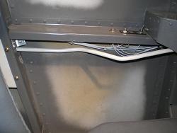 When
I first hooked it all
up, the
MS212532-4RS Clevis was bottoming out on the front throttle lever
before the lever was in the idle position. It took a little
extra
bend to get it to fit without interference. It’s hard to tell
from the pictures, but the pushrod stays pretty tight to the fuselage
skin until just aft of the F-804 channel, then it turns inboard and up
into the front throttle lever. When
I first hooked it all
up, the
MS212532-4RS Clevis was bottoming out on the front throttle lever
before the lever was in the idle position. It took a little
extra
bend to get it to fit without interference. It’s hard to tell
from the pictures, but the pushrod stays pretty tight to the fuselage
skin until just aft of the F-804 channel, then it turns inboard and up
into the front throttle lever.
Return
from Aircraft Throttle
Quadrant to Other
Mods
Return from Aircraft Throttle Quadrant
to Kit Plane Advice Home
|


 I
have short arms, and found the standard location of the aircraft
throttle was
too far forward and outboard. It was too uncomfortable for me
to
reach, so I felt like I was stretching to get to it. Since
it’s
my plane, it should fit me. I teamed with a friend
of mine
who also suffers from the same affliction, and we came up with our own
throttle quadrant that moved the throttle inboard and aft just enough
to make it comfortable.
 Because
I had moved the front throttle, the linkage to the rear seat needed
modifying too. I started by drilling the holes in the F-805-L
bulkhead as depicted in Template #1 provided with the Rear Seat
Throttle Kit. I bent a piece of scrap ¼ inch tubing to get
the
rough shape I wanted. I used this piece of tubing to enlarge
the
hole as needed until it could travel freely without scraping.
It
took a lot of cycles of bend a little, enlarge the hole, bend a little
more until I got the hole large enough, and the tubing bent correctly.
 When
I first hooked it all
up, the
MS212532-4RS Clevis was bottoming out on the front throttle lever
before the lever was in the idle position. It took a little
extra
bend to get it to fit without interference. It’s hard to tell
from the pictures, but the pushrod stays pretty tight to the fuselage
skin until just aft of the F-804 channel, then it turns inboard and up
into the front throttle lever.