|
Digitrak II Autopilot
This is specific advice on installation of the
Digitrak II Autopilot in a Vans RV-8. This could also prove
valuable to builders of other Vans kits or other aluminum kitplanes.
Mechanical
Installation
 Installing
the
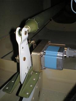
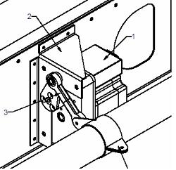
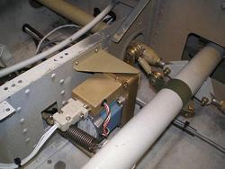
pitch trim went according to the plans. But the roll trim
drawing isn’t correct. It shows the bracket
backwards. This wasn’t a big deal. You can see in
the picture
how everything still fits. Installing
the
pitch trim went according to the plans. But the roll trim
drawing isn’t correct. It shows the bracket
backwards. This wasn’t a big deal. You can see in
the picture
how everything still fits.
The drawing showed how
long to make the pitch push rod. To be sure, I connected the
elevators, the F-841 push rod, and the F-635 elevator bellcrank to the
servo. Then I made sure it could travel from stop to stop
without reaching the limit of travel of the servo arm.
The
roll was a little harder. The drawing showed the push rod to
be only as long as the two ends. So I was assuming that was
the right length. I didn’t finish hooking it up until the
wings were mounted, and the ailerons fully installed and
rigged. Only then did I know the full travel of the WD-807
control column. Then I clamped the torque tube bracket to the
WD-807 with a side grip cleco and ensured I had full range of motion
and didn’t reach the limit of the servo arm. After I was
satisfied, I drilled the hole and used a blind rivet to hold the torque
tube bracket.
 
Wiring
I
started wiring the
autopilot at the bench. I had already measured, cut, and
marked the wires that needed to go into the d-sub connector.
Working in an upright position with good lighting is much easier than
on my back under the instrument panel (See Helpful
Hints for Soldering Terminals). After the panel end
of
the “bundle” was wired up, I threaded the other ends through the
bulkheads and conduit. See Use
multiple wire
bundles for what
I would have done differently.
Unfortunately the
smaller d-sub connectors don’t fit through the holes and
conduit. This means I had to wire them inside the fuselage.
 True
to form, I also
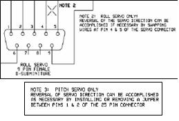
had to change the pins for the roll trim and add the jumper between
pins 1 and 2 for the pitch trim. According to the Digitrak
II Wiring Diagram Notes 1 and 2, if you need to reverse the direction
of the servos, you will have to make these changes. Murphy’s
law struck again, and I had to make both changes. True
to form, I also
had to change the pins for the roll trim and add the jumper between
pins 1 and 2 for the pitch trim. According to the Digitrak
II Wiring Diagram Notes 1 and 2, if you need to reverse the direction
of the servos, you will have to make these changes. Murphy’s
law struck again, and I had to make both changes.
If
your
servo installation looks the same as mine in these pictures, you should
start with main unit pin 21 to roll pin 4 and main unit pin 20 to roll
pin 5. You will also need to jump pins 1 and 2 on the main
unit.
Testing
I
tested the electric
connections by hooking
up the battery from my truck to power the unit. Don’t hook up
a trickle charger as it might ruin your electronics. The
small 3 amp power supply I had wasn’t enough to run the servos, so I
used the battery.
It was easy to check
the roll, I
just set the unit to HDG Hold, then turned the knob. The
autopilot tried to turn the plane to intercept the new heading.
The
pitch trim was a little harder because I had already mounted the
autopilot unit into my instrument panel and didn’t want to pull it
out. So I put the Digitrak II into ALT Hold mode and raised
and lowered the tail. This was enough to raise the unit
itself, causing it to move the elevators. I would suggest
keeping the unit out, where you can easily move it up and down to do
this test.
Return
from Autopilot
to Electrical Systems
Return from Autopilot to Kit Plane Advice Home
|


 Installing
the
pitch trim went according to the plans. But the roll trim
drawing isn’t correct. It shows the bracket
backwards. This wasn’t a big deal. You can see in
the picture
how everything still fits.

 True
to form, I also
had to change the pins for the roll trim and add the jumper between
pins 1 and 2 for the pitch trim. According to the Digitrak
II Wiring Diagram Notes 1 and 2, if you need to reverse the direction
of the servos, you will have to make these changes. Murphy’s
law struck again, and I had to make both changes.