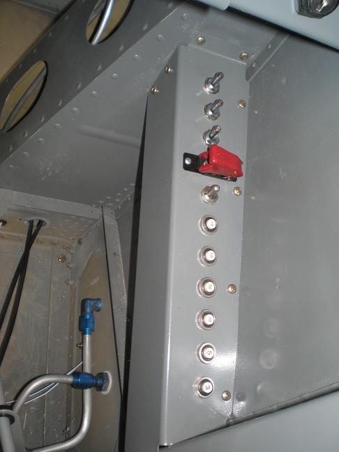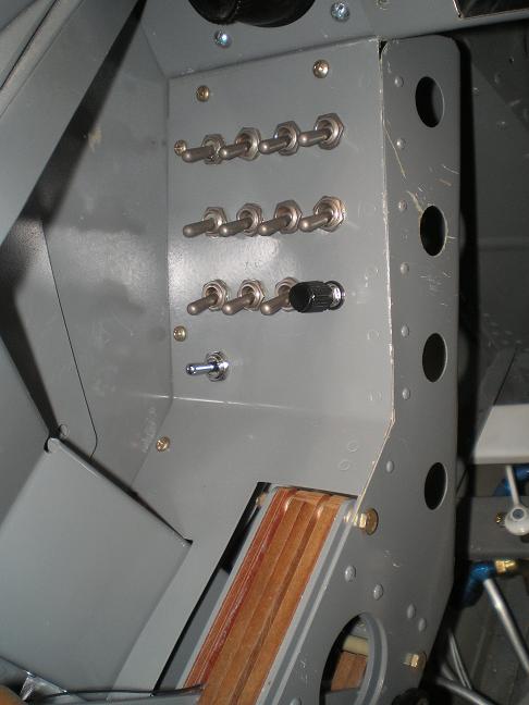

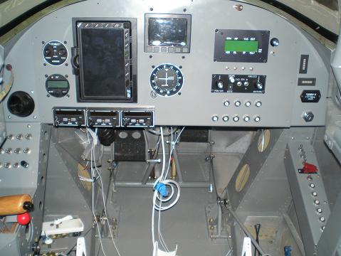
Building the Instrument PanelI put a lot of thought into the layout when building the instrument panel. There were certain things on wanted on the left and right sides. I spent a lot of time moving full-sized cutouts around until I had it just right before I ever made the first cut. I also made some key decisions on sub-panels and consoles. Here's how I did it.
General Layout Ideas First, a little on the layout of switches and instruments. I am right handed, so fly with my right hand on the stick and my left on the throttle. I want to take my hand off the stick as little as I can. I don’t mind taking my hand off the throttle, but not off the stick. I also don’t like swapping the stick to my left hand to throw a switch with my right. With this in mind, I designed the layout of my cockpit. I put switches and instruments that only need to be thrown before flight, or very seldom in flight on the right, and often used items on the left. Van’s electrical diagram shows combination switch/circuit breakers on the right console. Here is the only place that I disagreed with his “lighter and simpler are better” approach. I could have put combination switch/breakers on the left. I just don’t like the idea of turning things on and off with the circuit breaker. I think switches are for every day use, and circuit breakers are for overload protection. I think the added weight of separate switches and circuit breakers is a small price to pay to be able to put the switches on the left. I put things that I don’t
ever plan
on changing in the two
sub panels. On the
left, all I have is
the vent, and on the right, the ignition switch, By building the instrument panel in this way, I am able to update my panel without structural changes to the airframe, or unsightly leftover holes. I can buy a new main panel from Vans, cut and fit everything, while I am still flying with the old panel. Then on a rainy weekend, I can swap the two panels out.
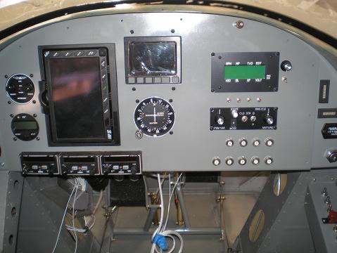
I also marked where the F-802T and F-802NPP L.G.box upper braces was behind the panel. Most of the instruments fit in front of them, but the Tierra radios are all too deep. They either had to go above or below the F-802T and F-802NPP. I made full size pieces that I could move around on the poster board until I was happy. Don’t forget to include the full size of each of your instruments, including the attachment brackets and other parts that will be behind the panel. I spent a lot of time with the cutouts, trying different layouts until I was happy. Don’t rush this part. You will be spending a lot of time looking at your panel. Make sure you are completely happy before building the instrument panel. My cutouts sat around the living room for a couple weeks while I played. I figured I was about ready when the wife got tired of seeing it. The only bracing required behind my panel was for the radios—everything else is small and light. By placing my radios just above the F-802T L.G.box upper brace, I was able to attach the back of the radio trays to the F-802NPP L.G.box upper brace, eliminating the need to build extra bracing.
I cut the squares with an angle grinder and a cutoff wheel. Then spent a lot of time with a file to clean up. Here's how the main panel turned out:
Sub Panels These were pretty straightforward. About the only comment I have is to cut as many holes as you can before you install them. It is much easier to drill and file at the work bench than hunched over in the cockpit. Left Sub Panel: 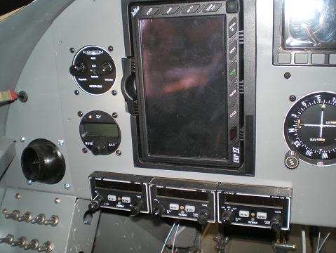
Right Sub Panel: 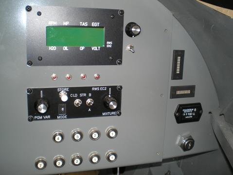
I followed the instructions for building the instrument panel on this one. My holes were placed exactly as described in the plans. If more holes are needed, I have seen multiple rows on other airplanes. They look good, but I bet they were a bugger to wire. It would get pretty tight under there.
By building my own throttle quadrant, I had the space to put switches for the lights, flaps, fuel pumps, etc. on the left, making them easy to access in flight.” Read here for more details on my custom throttle quadrant. I’m pretty happy with the way this all worked out. But, there are a few things I would have done a little differently when building the instrument panel. Click here to read about those.
Return from Building the Instrument Panel to Instrument Panel Return from Building the Instrument Panel to Kit Plane Advice Home |
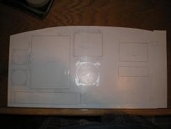 I
started by making my layout on a full size poster
board.
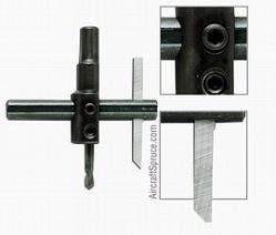 I
cut the round holes with a circle cutter like this one
from Aircraft Spruce.