Dynon EFIS
I installed the Dynon D10A Electronic Flight Information
System (EFIS) in my RV-8. Since all of their EFIS
systems
use the same components, this discussion would apply to them as
well.
There are three main components to install.
The main unit itself goes in the instrument panel, the remote compass
needs to be mounted somewhere away from magnetic interference, and the
outside air temperature (OAT) probe should not be mounted in direct
sunlight. Then they all need to be connected electrically.
The Main Unit
 I
purchased the flush-mounting bracket from Dynon to mount the unit in
the instrument panel. Because the edge of the hole will show,
I
spent a lot of time smoothing the hole and making it just big enough
for the unit to slip through. Then I slipped the unit into
the
hole and put the mounting bracket on from behind to get the exact
location of the mounting-bracket holes. Then I drilled holes
for
the screws that hold the bracket to the instrument panel.
After
everything was primed and painted, I screwed the bracket to the back of
the instrument, then screwed the bracket to the panel. The
only
down side to this setup is that I can’t pull the instrument out without
reaching behind the panel. Either I unscrew the bracket from
the
front and pull everything out from behind, or I have to reach behind to
unscrew the instrument, then I can pull it out the front. I
purchased the flush-mounting bracket from Dynon to mount the unit in
the instrument panel. Because the edge of the hole will show,
I
spent a lot of time smoothing the hole and making it just big enough
for the unit to slip through. Then I slipped the unit into
the
hole and put the mounting bracket on from behind to get the exact
location of the mounting-bracket holes. Then I drilled holes
for
the screws that hold the bracket to the instrument panel.
After
everything was primed and painted, I screwed the bracket to the back of
the instrument, then screwed the bracket to the panel. The
only
down side to this setup is that I can’t pull the instrument out without
reaching behind the panel. Either I unscrew the bracket from
the
front and pull everything out from behind, or I have to reach behind to
unscrew the instrument, then I can pull it out the front.
Remote Compass
 There
are two main spots I have seen remote compasses mounted—either
in
a wing tip, or in the aft end of the fuselage. I decided to
place
mine in the fuselage behind the baggage compartment. There
are two main spots I have seen remote compasses mounted—either
in
a wing tip, or in the aft end of the fuselage. I decided to
place
mine in the fuselage behind the baggage compartment.
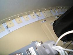
I
had purchased a mounting kit from Dynon for the remote compass, but
would not do that again. I would just make the bracket myself
out
of scrap aluminum. The best part of the kit was that it had
all
the non-magnetic hardware. I used an extra piece of AA ¾ X ¾
across the fuselage, and a triangle piece of .032 aluminum as a
gusset. Because I had the bracket from the kit, I used it on
the
other side to secure the aluminum angle and hold the remote
compass. I riveted all these parts into the fuselage.
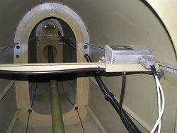
 I
used non-magnetic screws and nuts to hold the remote compass to the
bracket with washers where needed to shim a side. It took a
little doing to get the remote compass aligned with the main
instrument. They need to be parallel in all three
planes. I
measured from the F-808 bulkhead aft to the front of the remote compass
on both ends to ensure it was aligned with the yaw axis the same as the
instrument. I used a digital level to check “pitch” and
“roll.” The hardest one to measure was the pitch of the
instrument. I tried to measure the instrument
itself, but
it’s round shape made it hard to get a good reading, so I measured the
face of the instrument and the panel (which were the same) and then
added 90°. I
used non-magnetic screws and nuts to hold the remote compass to the
bracket with washers where needed to shim a side. It took a
little doing to get the remote compass aligned with the main
instrument. They need to be parallel in all three
planes. I
measured from the F-808 bulkhead aft to the front of the remote compass
on both ends to ensure it was aligned with the yaw axis the same as the
instrument. I used a digital level to check “pitch” and
“roll.” The hardest one to measure was the pitch of the
instrument. I tried to measure the instrument
itself, but
it’s round shape made it hard to get a good reading, so I measured the
face of the instrument and the panel (which were the same) and then
added 90°.
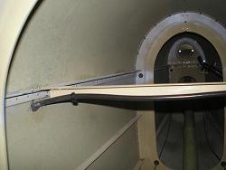
Because it was there, I used the aluminum angle cross
piece to support the static lines. But I’ll cover that in the
pitot/static
article.
OAT
 I
wanted to find somewhere out of the direct sun that would cause little
drag for the Dynon OAT probe. I decided that below the
horizontal
stab would be the best place. The OAT plugs into the remote
compass. Since I was planning on mounting the remote compass
behind the aft baggage compartment, this made the wiring a lot
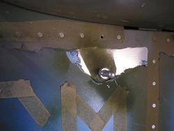
easier. A simple hole in the fuselage was all that
was
required for the OAT probe. I
wanted to find somewhere out of the direct sun that would cause little
drag for the Dynon OAT probe. I decided that below the
horizontal
stab would be the best place. The OAT plugs into the remote
compass. Since I was planning on mounting the remote compass
behind the aft baggage compartment, this made the wiring a lot
easier. A simple hole in the fuselage was all that
was
required for the OAT probe.
Wiring
I
ran the wire bundle from the main instrument to the remote compass down
the left gear box, below the floor, and through the tubing and
bulkheads as required. I ran the one wire bundle for the OAT
through the conduit along the left side of the fuselage forward to the
remote compass. The lines provided were way too long for me
to
just leave them, so I cut them to the correct length. Then I
crimped new tips onto each wire and pushed them into the d-sub
connector for the remote compass.
Because I had already
installed the turtle deck, I had to do all this work from the inside of
the tail instead of leaning over the side. This was
no
fun. Wire
as much as you can
before you put on the turtle deck.
Return
from Dynon EFIS
to Electrical System
Return
from Dynon EFIS
to Kit Plane Advice Home
|


 I
purchased the flush-mounting bracket from Dynon to mount the unit in
the instrument panel. Because the edge of the hole will show,
I
spent a lot of time smoothing the hole and making it just big enough
for the unit to slip through. Then I slipped the unit into
the
hole and put the mounting bracket on from behind to get the exact
location of the mounting-bracket holes. Then I drilled holes
for
the screws that hold the bracket to the instrument panel.
After
everything was primed and painted, I screwed the bracket to the back of
the instrument, then screwed the bracket to the panel. The
only
down side to this setup is that I can’t pull the instrument out without
reaching behind the panel. Either I unscrew the bracket from
the
front and pull everything out from behind, or I have to reach behind to
unscrew the instrument, then I can pull it out the front.
I
purchased the flush-mounting bracket from Dynon to mount the unit in
the instrument panel. Because the edge of the hole will show,
I
spent a lot of time smoothing the hole and making it just big enough
for the unit to slip through. Then I slipped the unit into
the
hole and put the mounting bracket on from behind to get the exact
location of the mounting-bracket holes. Then I drilled holes
for
the screws that hold the bracket to the instrument panel.
After
everything was primed and painted, I screwed the bracket to the back of
the instrument, then screwed the bracket to the panel. The
only
down side to this setup is that I can’t pull the instrument out without
reaching behind the panel. Either I unscrew the bracket from
the
front and pull everything out from behind, or I have to reach behind to
unscrew the instrument, then I can pull it out the front. There
are two main spots I have seen remote compasses mounted—either
in
a wing tip, or in the aft end of the fuselage. I decided to
place
mine in the fuselage behind the baggage compartment.
  I
used non-magnetic screws and nuts to hold the remote compass to the
bracket with washers where needed to shim a side. It took a
little doing to get the remote compass aligned with the main
instrument. They need to be parallel in all three
planes. I
measured from the F-808 bulkhead aft to the front of the remote compass
on both ends to ensure it was aligned with the yaw axis the same as the
instrument. I used a digital level to check “pitch” and
“roll.” The hardest one to measure was the pitch of the
instrument. I tried to measure the instrument
itself, but
it’s round shape made it hard to get a good reading, so I measured the
face of the instrument and the panel (which were the same) and then
added 90°.
 I
wanted to find somewhere out of the direct sun that would cause little
drag for the Dynon OAT probe. I decided that below the
horizontal
stab would be the best place. The OAT plugs into the remote
compass. Since I was planning on mounting the remote compass
behind the aft baggage compartment, this made the wiring a lot
easier. A simple hole in the fuselage was all that
was
required for the OAT probe.