Electric System Lessons Learned
or
What
I Would Do Different
I learned many electric system lessons as I installed
the various systems in my aircraft. Many of these ended up as
notes on how I would do things differently if I were starting again.
Perhaps these will give you some ideas for better ways to
build your airplane.
Wire
up
the tail before riveting the turtledeck
I didn’t have the luxury
of waiting
on the turtledeck until
after I had run the electrics. I
was
close to moving to Louisiana
and had a half-built fuselage. I
needed
to finish the turtledeck and the canopy to feel safe hauling it down
the
road. Most builders
will probably not
face this problem.
You can still accomplish
a lot of
building with the
turtledeck only clecoed on. The
ability
to remove the turtledeck will save you a lot of time and the pain of
crawling
into the back of the tail. With
the
turtledeck removed you can easily rig the entire elevator pushrod,
bellcrank
system. You can
also reach over the side
and drill the holes, run and clamp the conduit, and build and install
any
mechanical fixtures.
If I were able, I would
have done all
of the following
before riveting on the turtledeck:
- Built
and installed the longer
F-818C-L and R needed to hold the autopilot servo.
- Drilled
and primed all the
electrical holes
- Installed
the outside air
temperature (OAT) probe
- Built
and drilled the bracket for
the Dynon remote compass, but not installed it (I
think it would get in the way of crawling to the back to rivet, so
would save
it for later)
- Run
and clamped the conduit
- Pulled
the wires for the tail
lights, elevator trim, OAT probe, and remote compass
- Soldered
the d-sub for the remote
compass
- Drilled
and installed the static ports
Then after the turtledeck
was riveted
in place, I would
finish:
- Installing
the pitch servo on the F-818Cs
as I installed the F-635 elevator bellcrank assembly
- Installing
and connecting the
remote compass
- Installing
and connecting the
static lines
Wiring panel
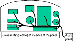 I am happy with my
wiring, it all
works! But I think
if I was to do it again, I would
make a change to make removing the main panel easier.
At the top of the left gear box, I would
install a plug panel with several d-sub connectors like in the picture. The panel would have
socket savers mounted to
it, providing male on I am happy with my
wiring, it all
works! But I think
if I was to do it again, I would
make a change to make removing the main panel easier.
At the top of the left gear box, I would
install a plug panel with several d-sub connectors like in the picture. The panel would have
socket savers mounted to
it, providing male on 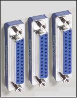 one side of the panel, and
female on the other. Then
all of the wire runs
to the airplane
would start there with a male fitting and go aft.
The wiring for the panel would start there
with a female fitting and go to the back of the instruments. I would run all the wires
from the
instruments into the center of the panel, then run the one large bundle
to the
left, then back to the d-sub panel. one side of the panel, and
female on the other. Then
all of the wire runs
to the airplane
would start there with a male fitting and go aft.
The wiring for the panel would start there
with a female fitting and go to the back of the instruments. I would run all the wires
from the
instruments into the center of the panel, then run the one large bundle
to the
left, then back to the d-sub panel.
I know this would add a
little
weight, but the ease of
maintenance provided would outweigh the penalty. It will also make
running the
wires easier. Measuring
the length of
the wire will be easier too because you will know exactly where to
start
measuring from at the panel end.
A quick look on the web
found everything
I would
need: socket
savers to go through the
panel, male and female connectors and their cases for the end of the
wire
bundles, nuts and screws. I
even found
a help document that has the size to cut the holes in the panel. I could connect
up my entire panel for about
$120. In fact, I
think the next time my
panel has to come off, I will do just that.
Use
multiple-wire
bundles
I ran individual strands
of wire for
everything. Next
time I would use multiple-wire bundles,
like Vans ES MSTS-WIRE. It
is the
six-wire bundle needed to connect the trim servos.
The autopilot, and possibly the intercom,
could
also be wired with multi-wire bundles.
Although this may
increase the parts
cost a little bit, it
will be a lot easier to install, and will weigh less.
You just need good measurements before you
order to ensure you get what you need, and not a lot extra.
Permanent Labeling
One of the biggest
electric system
lessons I learned was in wire labeling. I labeled my wires
with masking tape
while I was installing
them, and removed the tape as I crimped and fastened each wire. BIG MISTAKE! Now I have a bunch of
white wires that look
alike.
I would suggest
permanently marking
both ends of every
wire. If you use
multiple-wire bundles
with colored wires, you can label just the bundle, then list the colors
on your
electric diagram.
The technique I like the
best is the
use of different
colored shrinkwrap. A
single piece of
one color can be put on each end of a wire, or you can mix colors. For example, with just
three colors of
shrinkwrap, you can mark a 13 wire bundle like this:
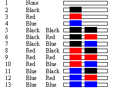
Mark
the wires on your schematic to match
the shrinkwrap, and tracing electric wires later will be a lot easier.
Mounting the Radio Trays
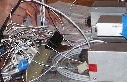 I
mounted the back of the trays to the F-802NPP L.G. Box Upper Brace with
a screw. I thought I had located it where it would be easy to
install and remove, but it was harder than I
thought. I
initially thought I would be able to easily reach the top of the
radios, but that isn’t the case. I have to remove my GPS and
its
mount to get to the screw for the radios. I
mounted the back of the trays to the F-802NPP L.G. Box Upper Brace with
a screw. I thought I had located it where it would be easy to
install and remove, but it was harder than I
thought. I
initially thought I would be able to easily reach the top of the
radios, but that isn’t the case. I have to remove my GPS and
its
mount to get to the screw for the radios. 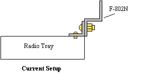 Otherwise,
with a lot
of difficulty, I can reach through the radio trays to get to the screw. Otherwise,
with a lot
of difficulty, I can reach through the radio trays to get to the screw.
The
next time I remove the instrument panel, I will change the
setup.
I will remove the small piece of angle aluminum I riveted to the top of
the radio trays, and will rivet it to the bottom of the
trays. 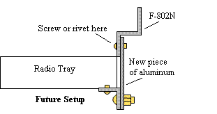 Then I will
screw or rivet a straight piece of aluminum to the back of
the F-802N that matches up to the angle. Then I can screw the
two
together from below the radio trays without effort. Then I will
screw or rivet a straight piece of aluminum to the back of
the F-802N that matches up to the angle. Then I can screw the
two
together from below the radio trays without effort.
Landing/Taxi
Lights
If I was starting a new project, I would check out
the new
Landing/Taxi/Wingtip combo lights.
Return
from Electric System
Lessons Learned to Electrical
Systems
Return from Electric Systems Lessons Learned
to Kit Plane Advice Home
|


