
Elevator and Aileron Electric TrimThis article talks about installing the electric trim in a Vans RV-8. Anyone installing a similar system in any airplane, especially another RV, will find this useful.
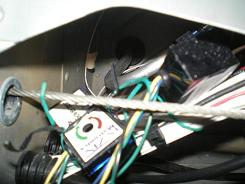
I used interlocking connectors from Radio Shack to connect the wires to the servos themselves. I think this is a little cleaner than having six splices right next to each other. Make sure you run the wires through the small hole in the EET-802 elevator trim bracket before you install the connector. Take my word for it, the hole is too small for the connector to fit through. I used the manual trim cable hole in the horizontal stab to run the wires for the electric trim. It would be a lot easier to drill the holes and install the bushings before the stab is riveted together, but if, like me, you do it later, you can still install a bushing from the trailing edge of the main spar. Mechanical Installation
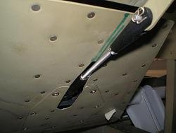
I
used a Dremel tool with
a small grinding bit to enlarge the inside of the SB437-4 snap bushing
enough
to allow the F-8109 slide tube to move freely.
The hardest part was the final installation of the second spring for the roll trim. I tried hooking the first end on the WD-807 and working the second onto the large cotter pin, but it ended up working easier the other way. I hooked the cotter pin onto the spring, inserted it in the hole, then worked the second end onto the WD-807. The first side of the spring hooked easy enough, but getting the second side hooked was tough. I ended up using two needle-nose pliers to hold the spring as I flexed it into position. I just kept working it until it finally went.
After everything was installed, I ran the trim full deflection one way and moved the controls full deflection in both directions. Then I ran the trim full deflection in the other direction and again moved the controls full deflection in both directions. That assured me that everything worked, and there was no binding anywhere.
Return from Elevator and Aileron Electric Trim to Electrical System Return from Elevator and Aileron Electric Trim to Kit Plane Advice Home |
 I
am using a
coolie hat switch on the stickgrip to activate
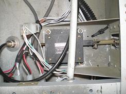
the trim, so I had to buy two ES MK-11, combination speed controller
and
relay
decks.
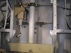
 The
mechanical installation
of the bracket was easy.
 Initially
I riveted just
the bracket and tube guide to the floor ribs.
 Installing
the elevator
trim was pretty uneventful.