
Wing Tip and Tail Strobe LightsThis is what I did to install the Vans System 6 strobe lights in my RV-8. This system consists of combination position/strobe lights for the wings, a white strobe for the tail, and one power supply. Even if you are installing different lights in a different aircraft, the ideas here can still help you out. I bought the Vans System 6 kit after going to Sun-n-Fun. The vendors there, and the Whelen representative, all said they could not beat the Vans price. Wiring I have two switches on my throttle quadrant, one for nav lights and one for strobe lights. The nav light wiring was straightforward. The power runs from the switch, through the left gear box, and under the floor. Just aft of the main spar it splits into three. The wing wires run through the wing conduits, and the tail wire runs through the conduit under the floor and aft on the left side of the fuselage. The strobe power follows the same route--through the gear box, then below the floor to the strobe power supply. The shielded bundles for the strobes run from the power supply, through the three conduits to the wing tips and tail. I want to be able to remove the wings without having to cut wires. So I used interlocking connectors from Radio-Shack at the wing roots.
Make sure you fit the lights so they are oriented along the longitudinal axes while the plane is in flight. I have seen builders make the mistake of installing the strobe lights level with the plane sitting on the ground—this is especially noticeable on a tail dragger. 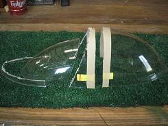 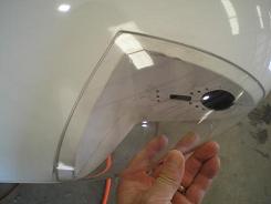 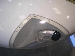
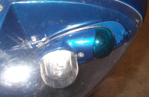
The next step was to fit the plexiglass covers. You can see in the picture how much I ended up cutting off. I took off enough to get close to start with, then I slowly worked my way to a good fit by trimming a little at a time. I temporarily installed the strobe lights while testing the fit to make sure the plexiglass cleared the strobe. One final note: I would chase all the platenuts before installing them. They are way too tight to begin with. I didn’t, and when I was screwing the cover on, one of the rivets ripped out. So I had to remove the wingtip to repair it. Update: After my first flight, I saw that the heat from the strobe lights had started to warp the clear plexiglass covers (see the picture). You can see the warped portion just in front of the green lense. So I have moved the entire fixtures as far aft as possible. This left the front of the old hole showing, so I made a cover plate of aluminum. I painted the aluminum plate the same color as the blue of the wingtip, but by angling the bright flash, I got the aluminum to reflect enough so you can see it in the picture. If you are going to install these types of lights, I suggest you install them as far aft as possible the first time.
Tail Lights 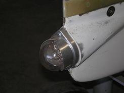
Fitting and drilling the tail light was relatively simple. The only real issue was the limited space. Initially I thought I would be able to use platenuts to secure the light, but there just isn’t room inside the rudder tip. So next I thought I would be able to reach the nuts with a socket, but there wasn’t even room for that. So I ended up gluing the nuts in place on the inside of the tip. I put two cheap screws through the holes and tightened the nuts down. Then I put some masking tape around the hole to act as a dam for the epoxy. I mixed a little fiberglass epoxy with some micro-balloons to make it a little stiffer and packed it around the nuts. When it was dry, I removed the screws and did a little bit of sanding to clean up the drips of epoxy. What I Would do Different 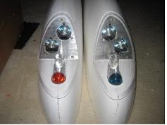
When I built my wings, Vans did not offer the LL 7/8 MR-16, RV-7/8 Wing Tip Landing Light Kit. If I had the option, I would look into this all in one system. It would probably be cheaper, lighter and easier/quicker to install than using the two separate landing/taxi lights and wing tip lights.
Return from Strobe Lights to Electrical System Return from Strobe Lights to Kit Plane Advice Home |
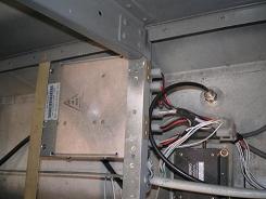 I
spent some time trying to fit the power supply into different parts of
the plane. It came down to two spots to choose
from. Just behind the aft luggage compartment, or
below the floor. I
chose to install the power supply below the F-830PP left floor, just
aft of the F-805B-L. It was easier to install upside down,
but this meant I had to remove the cover and drill a drain hole in the
new bottom aft corner.
 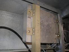 I
riveted an aluminum angle left to
right between the F-815-L and F-814-L aft of the F-805B-L to attach the
aft end of the power supply. Two aluminum angle brackets are
riveted to the F-805B-L and two to the new piece of aluminum
angle. A bolt and nut through each bracket and the power
supply lip holds the power supply secure.
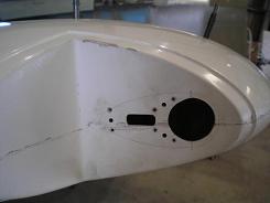 I
started by drilling the holes for the light fixture in the
wingtip. I didn’t have a drill bit large enough for the big
hole,
so I used a drimmel tool to make it the final size. I made
the
square hole by first drilling a hole, then filing to final shape.