
Wing AssemblyThe Wing Assembly consists of the spars, the skeleton, and the skins. Spars
Vans has you separately priming every little subassembly. I waited until I had a few subassemblies before I primed them all together. I did all the countersinking on the main spar, made the tie-down assemblies, and completed all the rear spar fitting and drilling before I primed everything at once. Skeleton
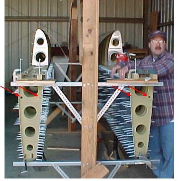
I did not rivet the inboard two ribs on each wing assembly until after the bottom skins were riveted. The top skin would have been no problem, but it would have been tough to reach inside between the ribs to rivet the bottom skin. While you have them all clecoed together, try putting your hand between the first three ribs while maneuvering a bucking bar; it’s not easy. The ribs were just too close together. It was much easier to push them in from the end of the wing and rivet them in place one at a time. At this point, I put the wing assemblies into the jig. See jigs for my ideas. I spent some extra time here making sure everything was square. The directions talk about holding up the middle of the wing until the row of rivets is straight. This ensures the wing is straight, but not square. I also used a level across the top of the spar, and shimmed until it was level. Then I put the level against the end ribs and clamped them in place to ensure they were square to the main spar. The last thing was to check that I hadn’t added any twist to the skeleton. I dropped a plumb line down and lined up the tooling holes on the end ribs. Only after I was sure the wing was true did I start with the skins. After the wing assembly skeleton is square and true, the main skins can be clecoed on and all the holes drilled to final size. You should be able to push all the ribs around if needed to line up with the holes in the skins. Don’t install the platenuts for the access panels yet. You will be reaching in through the holes while riveting the bottom skins onto the skeleton, and the platenuts can get in the way or cut up your arm. It’s now time for the tank jig discussed in Jigs. You will use it to cleco together the leading edges. After they are clecoed to the main spar, recheck them for square and true. The tooling holes should again line up, and a level placed against the inboard and outboard ribs should show level. Now it’s time to move from main wing assembly to the Wing Tanks.
Return from Wing Assembly to Wing Kit Return from Wing Assembly to Kit Plane Advice Home |
 You
will start the
assembling the
wing parts by riveting the
tank attachment platenuts to the main spar.
 You
have
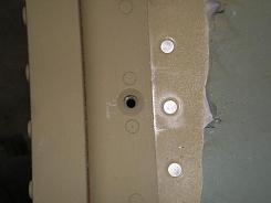
to take off so much metal, that the hole will open up, and the
countersink bit
will start wondering.
 Initially
I drilled only the holes in
each rib for the electrical conduit. Since all the ribs don’t go in the
wings
facing the same way, I drilled top and bottom of each rib.